In electronic circuit design, every parameter of a crystal oscillator is crucial to the product's success—even a 0.1ppm error can derail an entire board. These seemingly basic terms are actually invisible barriers that hardware engineers must overcome daily.
Due to the length of the article, it will be explained in two separate articles. This article is the second part, covering the following topics:
· Resonant frequency
· Crystal oscillator terminology
> Resonant frequency
Product descriptions mention three pairs of resonant frequencies: "series resonant frequency" and "parallel resonant frequency" (fs and fp), "resonant frequency" and "antiresonant" frequencies (fr and fa), and "maximum and minimum total susceptance positioning" frequencies (fm and fn). These frequencies can all be derived from the lumped equivalent circuit parameters shown in Figure 9. The definitions and relationships of these three pairs of resonant frequencies can be clearly illustrated in the complex admittance plot shown in Figure 10.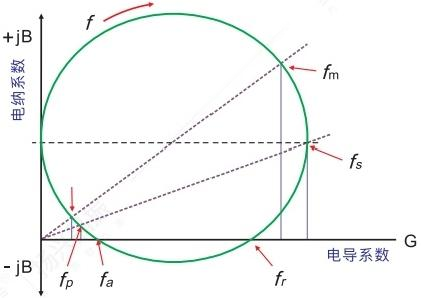
(Figure 10) Resonant Complex Admittance
Key frequency parameters of a quartz resonator can be determined through admittance and impedance analysis:
Series resonant frequency (fs): The frequency at which the input conductance (real part of the admittance) is maximum. At this point, the crystal oscillator's impedance reaches its minimum and becomes purely resistive.
Parallel resonant frequency (fp): The frequency at which the input resistance (real part of the impedance) is maximum. At this point, the crystal oscillator's impedance reaches its maximum and becomes purely resistive.
Resonant frequency (fr) and antiresonant frequency (fa): The two frequencies at which the susceptance (imaginary part of the admittance) is zero. These are key parameters in practical applications.
In the equivalent circuit:
Dynamic parameters: The dynamic capacitance (C1) and dynamic inductance (L1) determine the resonant characteristics.
Static capacitance (C0): Parasitic capacitance in the parallel branch, which affects high-frequency response.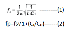
> Terminology
1) Nominal frequency and its tolerance or calibration accuracy
The frequency of a crystal resonator is specified in MHz or kHz and refers to the "normal frequency" expected in a matched oscillator circuit with a specific load capacitance. The maximum allowable deviation of the measured frequency from the nominal value at a reference temperature of 25°C is given in percentage (%) or parts per million (ppm).
2) Fundamental Tone and Overtones
Thickness shear vibration is the main vibration form of AT cutting angle. The high-order harmonic vibration between the electrodes coexists with the fundamental frequency vibration. Due to the opposite polarity of the two electrodes, the piezoelectric quartz crystal can only excite odd-order harmonic vibration. 晶体谐振腔只能激发奇数次谐波振动-834224.png)
(Figure 11) The crystal resonant cavity can only excite odd-order harmonic vibration
3) Load Capacitance
The load capacitance CL is the load shown by the oscillator when the circuit is viewed from both ends of the resonator. The load capacitance is connected in series or parallel with the resonator. In the case of parallel load, the presence of CL affects the parallel resonant frequency, and the parallel resonant frequency fL is given by. The formula is as follows.
fl=fs√1+C1/(C0+CL)-------(3)
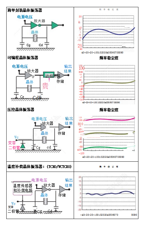
4) Frequency-Temperature Stability
Frequency-temperature stability refers to the frequency offset (in % or ppm) caused by the change in operating temperature with a reference of 25°C. Its curve reflects the corresponding relationship between the offset and temperature deviation, which is determined by the cutting angle, vibration mode, chip size, operating temperature range, load capacitance and drive power.
5) Equivalent Series Resistance (ESR)
The resistance R1 (Figure 9) present in the series branch can be measured at the series resonant frequency. At this frequency, the effects of C1 and I1 cancel each other, and R1 represents the mechanical losses of the crystal unit and package.
6) Motional Capacitance C1 and Motional Inductance L1
The two parameters, C1 and L1, are related to the series resonant frequency fs, as shown in Figure 10. fs is a highly specific parameter in resonator design and characterization. Industry standards only specify the value of C1; L1 can be derived from the following formula. Compared to capacitors typically used in oscillator circuits, the value of C1 is very small and can be estimated based on the material and geometry of the crystal and electrodes.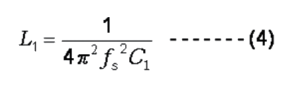
7) Static Capacitance C0 (in the branch)
C0 is a static capacitance that exists regardless of crystal operation. Its value can be measured at very low frequencies (less than or approximately 1.0 MHz) and is calculated using the following formula:
A is the electrode area, d is the slice thickness, and e is the dielectric constant of the corresponding crystal slice. In practical applications, C0 includes not only the static capacitance of the plated quartz die, but also the capacitance of the conductive bonding material and the capacitance of the package itself.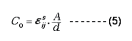
8) Drive Power
The drive power of a resonator is the power consumption measured in nanowatts, microwatts, or milliwatts. The operating power is the appropriate power range to ensure proper startup and maintain steady-state oscillation. The drive power should be set to the lowest power to avoid frequency drift and crystal damage caused by long-term operation. The smaller the crystal size, the lower the maximum tolerable drive power. In most cases, a drive power of 10 µW–100 µW is recommended.
9) Quality Factor (Q)
For resonators, the quality factor (Q) is a very important parameter. Specifications specify the Q values under no-load and loaded conditions. No-load Q, or mechanical Q, can be expressed as follows: R1 is the resistance in the series branch. The load value depends on the load circuit.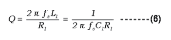
10) Pull-Down Ratio
In a parallel-loaded capacitor oscillator, the oscillation frequency is related to the load capacitance, CL, as shown in Figures 8 and 12. The frequency change (in ppm) as a function of the load capacitance change (in pF) is fixed. In some applications, a change in the load resonant frequency is mandatory (e.g., VCXOs), requiring a specified pull-up rate.频率变化vs负载电容-619559.png)
(Figure 12) Frequency Change vs. Load Capacitance
11) Aging
Aging refers to the relative shift in the operating frequency over a specified period, measured in ppm, decaying exponentially. The change is fastest during the first cycle and then slows down. Commonly used accelerated methods include storage at 85°C for one month or at 25°C for one year. The aging rate is affected by the packaging method, seal integrity, process, materials, operating temperature, and frequency.
12) Storage Temperature Range
The storage temperature range refers to the extreme low and high temperatures that a crystal can withstand for extended periods when powered off. As long as this range is maintained, all specifications should still meet the specifications when restored and operating within the rated temperature range.
13) Negative Resistance - R
Negative resistance is the equivalent resistance presented by the oscillator circuit at the resonator terminals. One of the necessary conditions for oscillation is that the amplifier provides sufficient gain to offset the loss of the resonant cavity; for the resonator, the load must present a negative resistance large enough to compensate for its own resistance.